2016年4月26日 星期二

Step 7: Create Aluminium Adhere

The shape of brick can be seen as a cube with extensions. After discuss with the lecturer, I decided to make two separated aluminium adhere to show both detail on the top face and side.
The actual object and the 3D template


The Top Adhere:


The shape of the top surface is formed with two significant negative space. Instead of getting a ruler and measure how much aluminium sheet I need for my adhere, getting a thin strip folded into the shape would be easier.


The dimension of the unfold strip is the length I cut my aluminium sheet.


After knowing the measurement from the stripe, I manually cut the 1mm aluminium sheet into a smaller piece (slightly bigger than the area I need)


Roughly fold the sheet with the shape of the shape done previously. The shape needs to be constructed from the middle to the side. It will be impossible to use the folding machine if the process goes from one side to another. 


Slightly smoothen the folded bit by hammering the sharp edge. (Do not band the aluminium sheet from both side or re-band the same area over and over agin, the sheet may crack) 


Find a metal tool that's similar to the size of the negative space and giving force from the top by hammering to the aluminium sheet. 


This process allows the sheet to be more obedient to the shape of the template, also adjust the size of the curves. 


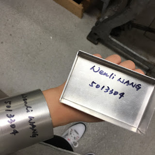
Completed adhere for the top surface of the template


The Side Adhere:
(first attempt)


Cut the aluminium sheet into suitable size for the object


Measure and mark the four holes on the template. Roughly hammered the negative space against a sandbag.


The negative spaces are unsymmetrical with sloping surface deep in the hole. In order to achieve the shape perfectly, you are required to make a special tool to hammer against with. (ask the supervisor for help when using the tool making machine)


The special made tool.


Place the tool under the spot you wish to be deeper on the sheet and beat around it with a metallic hammer. (the reason for choosing metallic hammer is to shorten the time making extreme shape in shall surface)


Front view of the hole


Back view of the hole


The special tool helps to achieve the shape quickly, but you need to hammer the shape carefully. In this case, the aluminium sheet was cracked by pushing the shape too hard in one go.


I decided to make another adhere. The place where it cracks is hard to be pushed any further.


(second attempt)


Cut the aluminium sheet in suitable size for the side surface (needs to be slightly bigger then than the actual size, the sheet ill shrink while making the negative spaces in the center)


Mark the four negative space with black marker and hammer the shape with a rounded tool over the sandbag (needs to place on something soft to allows the sheet to bend)


Cut the top edge with two "u" shape to fit the surface of the template. 


Mark the edge of the two sides and manually band the extra sheet into 90 degree angle (this also helps the adhere to attach to the template)


Smoothen the top and bottom edges with equipment.
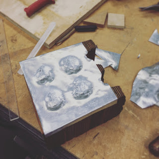


Attach adhere to the 3D template, fixed the lumpy surface with hammer that contains a flat metal side. 


Also push the sheet harder to show more details of the negative space (the adhere can be beaten over the template carefully with a wooden hammer)


You can use the special tool made in the first attempt, but don't try to achieve the shape in one go, the aluminium might crack again.


Completed adhere for the side surface of the template


Check the side of the model to see if the aluminum adhere fits to the template 

Step 6: Assemble the Template

Assembling the template is simple, all you need to do is remove pieces from the material board and glue together in order.


place in order
(the bigger number goes to the top)


glue pieces by layer
(the small complex piece can be lined up with the construction lines on the previous piece)
The completed 3D template


Step 5: Laser Cut

There are two parts in this step, one is making minor changes to the file to get ready for laser cut, the second part is to do the cutting.


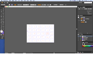
Open the dxf file in Illustrator:


1. change the size of your paper to fit your material board.
     (900mm x 600mm in this case)

2. rotate laser cut template to fit the paper

3. delete the invisible line on the edges of the paper.
     (the step can avoid laser going along the edges and cause ugly burn on the material
     board)

4. exchange the colour of blue and red lines.
     "Red" line means "cut" and ""blue" line means to mark lightly on the surface of the  
      material. You would like the outline of the stacks to be in red for cutting and the  
      notes and numbers in blue for marking

5. highlight every single line on the page and make the front into 0.05 mm, which will  
    automatically changes the number into 0.14...... (this is the standard width of laser cut)

6. save the file in ai 


Laser Cutting:

Import the ai file into laser cut machine. It takes about 20 minutes to finish the laser work. 

laser cut machine


processing


It is important that you stick along the parts on the board with masking tape before removing the material from the machine, otherwise the small pieces might be falling into the exhausted grid under the machine.


Step 4: Create Sections for Laser Cut

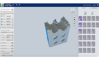
Import the stl file into 123D Make from the previous app. In this step we will complete a laser cut template that is ready to open in illustrator for cutting. All the settings including size of the material board, cutting techniques and construction will be done here.


Original file:


On the left tab:

1. change the scale to "mm"

2. select the size you wish to make your object
    (it's in uniform scale, you only need to change one dimension)
    hammer and other tools for making the aluminium sheet are mostly 10cm x10cm, you 
    get your life easier if you have a larger template

3. select the "construction technique" that is appropriate to show details of the object
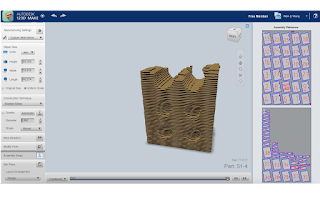
    (stacked slices in this case)

4. fill in the size of the material board you're using in "manufacturing settings"
    (it can be any material permitted for laser cutting)
    material used in this case is 900mm x 600mm x 3mm 
    the thinner the material is, the more detail it shown

5. save the file in dxf for the next step


Completed object with laser cut layout:


Step 3: Modify the 3D Scan

Download the object scan from the Autodesk account and import to the Meshmixer (app available from the autodesk website)


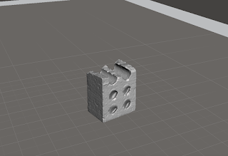
The completed object will be look like:


Beside the object itself, everything extra including the flooring and background need to be removed. Holes and gaps can also be filled and polished here (see demonstration below). 

After modifying the object, the file needs to be save as stl to allow the access from 123D Make.


Removing/ Deleting parts:


1. choose "select" from the left tab

2. adjust the brush to appropriate size

3. circle the extra parts
    (it will appears in red line)

4. press "delete" 


After editing the model, check every edge and corner on different surface wether if there's still any gaps or additional parts that need to be deleted (needs to be done carefully, unknown holes might cause failure next step). 

Save the file in stl.


Step 2: Creating Scans by 123D Catch

123D Catch is a free app that you can download from the autodesk website. I personally suggest installing the app on phone instead of laptop as it actually gives you a double circle track that guides you through the photographing process. The angle of the photograph taken by phone is more accurate than taking random photos then upload to the laptop to check.  Basically, you only need to take photos around the object follow with the angle guide on the left corner and wait the scans to be upload and made. Also, it takes about 1 to 2 hours to run an object scan, doing this on phone means you don't need to sit in front of your desk and wait forever. 


First attempt:
It takes around 1 hour to run the whole process, but the result is failure. I was told by the lecturer that lightbulb would be really challenging object to scan on 123D catch as its is white and reflective. However, I would like to try and see how much it shows on the app. 


The image turns out twisted and half collapse. The metal and plastic part of the lightbulb comes out in a funny shape, but this can be fitted with a better photographing skills. The main concern is the top rounded bit, it doesn't even show up in the scan result. 


Second & third attempt:
I wrapped around the top of the lightbulb with yellow masking tape and redo the 123D catch. 


The matt surface of the masking tape allows the top part to be shown, but the metal part and other half of the body are still missing. The issue causing failure might not only due to the color and reflection, but also the shape of the lightbulb itself. The rounded shape creates glow with any illumination, even if it's wrapped around with matt surface tape. After three attempt, I decided to change my object.


Fourth attempt:
The fourth attempt was successful, brick is much more easier to be made than the lightbulb. The red solid form and rough surface allows the outline and shape of the brick to be indicated easily. The details and breaking part are well captured with no gaps and holes. 


Step 1: My Chosen Object

Every interior space around you are designed thoughtfully from the designer. From a retail space, a house to a museum, they actually comes with a long process. As an Interior Architecture student, we are trained to provide comfortable and athletic spaces for the client. Before designing a space, we research its site and analysis the function and purposes to propose the suitable structure apply with the right material, lighting and decoration. 

My chosen object is something that related strongly to my discipline. It is not only a fundamental of architecture, but also something we learn, analysis and work with before designing the space. 

The first object I choose was a lightbulb. Lighting and materiality are the most important elements of forming an interior space. Without the illuminations, non of the structure and details will be seen. Moreover, a successful lighting design endows emotion and atmosphere to the space. Different types and brightness of the illumination deliver different kinds of living experiences. 


Due to the difficulty of making a 3d scan, I decide to change my object (see the experimentation in next article). 

My second chosen object is a brick. "Essential is greater than the circumstantial", said Louis Kahn. Knowing the essential of building, the nature of the material is necessary before design and constructing the architecture. People who walk into the space might draw his eye on the colour and decoration, but as an architect or a designer, we produce the space from stacking bricks and shaping the structure. 


The reason to break the brick and only using half of it is to get interesting curve from the block that challenges the making.

2016年4月25日 星期一

Assessment 1: Brief & Steps

The assessment brief is to create an aluminium skin to adhere the contours of a 3d template based on a disciplinarily relevant found object. 

Steps to complete the task:
1. choose an object related to the discipline
2. create a 3D scans of the chosen object by 123D Catch app
3. modify the scans with the Meshmixer 
4. create sections for laser cut model by 123D Make
5. laser cut the model
6. assemble the model to form a 3D template
7. create an aluminium adhere to the the 3D template 


Before starting the assessment, online modules including basic workshop induction and FabLab workshop induction need to be completed to access the studio lab.laser cut and 3D printing workshop
metal sheet workshop